Loads - Nodal Loads
RISAFoundation allows nodal loads to be oriented along any of the global axes or applied as a point moment about those axes. Nodal loads with a positive magnitude are applied in the direction of the positive global axis they are assigned to, and negative loads are applied in the direction of the negative global axis. The exception to this is that loads applied along the global Y-axis are reversed (i.e., positive loads are applied in the direction of the negative global Y-axis and negative loads are applied in the direction of the positive global Y-axis). All point moments are applied about the global axes according to the right-hand rule, including MY moments.
Drawing Nodal Loads
Nodal Loads and Nodal Moments are concentrated loads and may be placed anywhere on a slab or beam. Nodal loads may be assigned manually in the Nodal Loads and Moments Spreadsheet or drawn graphically in a model view.
Click on image to enlarge it
To draw Nodal Loads:
-
If there is not a model view already open, choose the Add 3D View option from the Open 3D Views drop-down on the View ribbon.
-
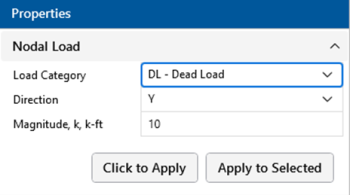
Click the Nodal Loads icon on the Home ribbon and define the load in the Properties panel.
Click on image to enlarge it
-
You can choose to apply the load to a single node at a time or to an entire selection of nodes.
-
To apply the load to just a few nodes, click the Click to Apply button, then click on the nodes in the 3D View with the left mouse button.
-
To apply the load to a selection, click the Apply to Selected button.
-
- To apply more loads with different parameters, change the parameters in the Properties panel and choose Click to Apply or Apply to Selected to apply the new loads.
- You can also specify or edit nodal loads in the Nodal Loads Spreadsheet.
- You can undo any
mistakes by clicking the
 Undo button.
Nodal Load Spreadsheet
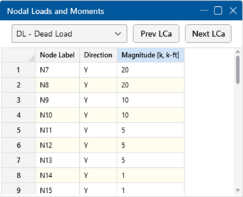
The Nodal Loads Spreadsheet records the nodal loads on all slabs and beams and may be accessed by selecting Nodal Loads from the Data Entry drop-down on the Spreadsheets tab of the ribbon, or by clicking Nodal Loads on the Data Entry toolbar.
Click on image to enlarge it
The first column contains the Label of the node to which the nodal load is applied.
The Direction column defines the direction of the nodal load or moment relative to the Global Axes.
The load Magnitude is recorded in the third column. The units for the magnitude are listed at the top of the column, depending upon whether the load is a force or a moment.


